Manufacturing Dental Implants using Powder Injection Molding
Ferreira TJ, Vieira MT, Costa J, Silva M and Gago PT
1CEMUC – Centro de Engenharia Mecânica da Universidade de Coimbra, Portugal
2IPN – Instituto Pedro Nunes, Coimbra,Portugal
3DTech – Marinha Grande, Portugal
- *Corresponding Author:
- Ferreira TJ
CEMUC – Centro de Engenharia Mecânicada Universidade de Coimbra, Portugal
Tel: +351239 790700
E-mail: tferreira@student.dem.uc.pt
Received date: December 09, 2015; Accepted date: February 18, 2015; Published date: February 22,2016
Citation: FerreiraTJ, Vieira MT, Costa J, et al. Manufacturing Dental Implants using Powder Injection Molding. J Orthod Endod. 2016, 2:1.
Abstract
During the last decennia it is demonstrated that the injection molding used in polymers could be the solution to decrease the price of parts / devices of metallic alloys for large-scale series production. The metal powder injection molding (MIM) technique has five main steps: selection of powder and binder, production of feedstock, injection molding, debinding and sintering. The material selected was the 316L steel due to its wide use as biomaterial associated to low cost of powders and its high injectability. The feedstock was suitable optimized and produced by torque rheometry technique. The ideal feedstock has 60:40% vol. of powders:binder and has low torque value (suitable to injection step). It is important to decrease the friction coefficient (between the molding parts and mold surfaces) and to improve significantly the wear strength of mold surfaces. The (micro) mold was designed and developed for producing dental implants in large series that means coated with a high hardness and near frictionless thin film of dichalcogenides sulphides (W-S-C). The injection step was carried out at 10MPa and the binder was efficiently removed from green implants. After sintering step (at 12500C), dental implants have a good finishing and the shrinkage of dental implants was evaluated. The osseointegrability was promoted by coating the sintered implants with a thin film of non-modified and Si modified hydroxyapatite (HA). The coated dental implants were mechanically evaluated during implantation using a bovine rib. The new strategic production leads cheaper implants, called "implants for crisis", where surface modification assures a similar or superior bioactivity than commercial implants.
Keywords
Powder injection molding; Dental implants; 316L powders; Micro mold; W-S-C coating; HA thin films
Introduction
Dental implants existed for many years and they include artificial teeth to restore the natural dental function [1]. Conventional dental implants are typically made in metal and metal alloys, where titanium and its alloys have an important role. Besides the high cost of these materials, the traditional manufacturing systems are expensive having in mind the number of implants to be produced and their complex shape [2].
Currently, there is a need to improve the method manufacture of dental implants, making them cheaper and fast manufacturing [1]. In order to investigate alternative cost effective manufacturing methods for producing dental implants, MIM technique was evaluated. The MIM is regarded as very promising net shaping technique, due to its advantages for complex geometry, precision and production in large-scale series of implants with high performance, without finishing process [3]. The MIM technique have five processing steps, namely: raw material characteristics (4S's = particle size, particle distribution size, shape and structure), mixing of powder and binder for feedstock preparation, injection molding of feedstock to the desired shape, debinding to remove the binder and sintering to give the required properties [3-5]. The thermal characterization of the binder is very important to know the melting and degradation temperatures, to define the processing conditions for mixing and injection, as well as for debinding cycle. In the feedstock preparation is essential that all the metallic powders are involved / coated by binder and suitable viscosity for one injection step adequate. The binder content in feedstock must be optimized in order to have a suitable viscosity value and after injection and debinding (necessary to produce a metallic part / device) to maintain the geometry before sintering.
Among the big challenges facing MIM, the (micro) mold is unquestionably one of the most relevant, because of its quality depends on the success or failure of this technology. The molding blocks for injection molding, usually consist in inserts (cavity and core) micro machined and assembled on a standard structure. While the mold’s structure and its injection systems are manufactured by conventional processes, other techniques are used for manufacturing the molding surfaces. The manufacture of (micro) molds uses subtractive micro machining technologies that can create 3D micro geometries, in some cases, with high-precision and aspect ratio, like micro-milling, laser beam machining (LBM), micro electric discharge machining (μEDM) and, as polish / finish technology, electron beam machining (EBM) [6]. All of these techniques, micro-milling is the most versatile and able to produce complex 3D shapes, but quite problematic in details below than 0.1 mm. The μEDM and, especially the LBM, will produce a thermal affected layer, therefore not ensuring the desirable texture and integrity surface for the generality of applications, but this limitation can be resolved with the use of EBM. Note that finishing by EBM promotes significant resistance to oxidation and corrosion, when compared with conventional surface treatment processes [7].
One of the critical steps of injection molding is the extraction of the implant from (micro) cavity. During the extraction steps, the parts are mechanically forced to separate from the molding surface and this aspect is more relevant in the case of deep cavities. The design of the ejection system depends on several factors: draft angles, surface finishing, properties of the material to inject and temperature during the ejection step [8].
Other main existing problems in the manufacture of the teeth implants is based on the ability to process high quality surfaces with minimal roughness values associated to the dimensional precision tolerances, which are fundamental to the micro scale. Moreover, the injection of metallic feedstock is more abrasive than the polymeric ones, which difficult the outflow during injection and consequently, the extraction process of small components. In order to overcome this critical issue, coatings referred to as “near - frictionless” as Dichalcogenides Sulphides are an optimal solution [9, 10]. They are well known for their crucial role in reduction of mechanical and abrasive wear and by exhibit low friction coefficient, which is relevant to promote the extraction from the coated mold of implants. The sputtering technology used on the development of this type of coating, which belongs to the group of additive processes called Physical Vapor Deposition (PVD), is a versatile technology that enables developing coatings with suitable chemical compositions and homogeneous growth over surfaces to protect / modify them, responding effectively to the challenges in the manufacture of molds for micro-components or molds with micro details.
The MIM technology can help to produce cheap dental implants, however it can be necessary to improve the rate of osseointegration e.g. through implants coated with nano hydroxyapatite (nanoHA) with or without silicon addition. There are studies reporting that HA doped with specific elements (titanium) has advantage in biological process [11, 12]. Therefore, HA based coatings were selected due to their good performance in osseointegration behaviour
The main objective of the present study is to show the potential of injection technology for producing metallic dental implants from metallic powders, highlighting the engineering solutions for the manufacture of micro-molds coated with W-S-C to improve the performance of ejection step and minimize the force to separate the parts from the molding surface. Were produced dental implants by MIM from powders of austenitic stainless steel (SS 316L). The sintered dental implants were physical and mechanical characterised and the torque strength of implants was evaluated using as counter body a bovine rib. The dental implants produced were coated by nanoHA with various contents of silicon.
Materials and Methods
Materials
In this work, the metal powder used was water atomized 316L austenitic stainless steel - SS316L (Epson Atmix Corporation®) and the multi-polymeric binder based on polyolefin waxes (from Atect®). The material used for producing the (micro) mold was a steel DIN X40CrMo V5 1 (48 to 52 HC).
The molding blocks were coated with Dichalcogenide Sulphide coating W-S-C. They were deposited by co-sputtering from two WS2 and one Carbon targets in an unbalanced - sputtering unity (Teer coating equipment). A fourth Chromium target was used as interlayer step, in order to improve the coating adhesion to SS substrate. Finally, dental implants were coated from HA target using rf sputtering.
Methods
The mixture of metallic powder and binder was optimized by torque rheometry technique in Brabender Plastograph mixer, for suitable evaluation of the critical powder volume concentration (CPCV), at programmed temperature and rotational speed [5]. After optimization, it was possible to select the suitable powder: binder ratio for produce feedstock and this was evaluated by controlling the torque value during the mixture process and by SEM micrographs. Finally, the feedstock was granulated into small granules promoting the homogeneity and enabling feed when carried out the injection molding, into a mold cavity with shape of dental implants in Arburg 270C injection molding machine. The debinding and sintering thermal cycles, were carried out in a high temperature oven, under controlled atmosphere of 95% argon and 5% hydrogen. The debinding cycle was based on binder thermal analysis and the sintering conditions were carried out according to the selected powder.
The μmold was produced by the following subtractive technologies: μmilling, μEDM and EBM. The μmilling machining was performed on high-speed CNC micro-machine (Deckel Maho Gildmeister), with a maximum spindle speed of 36000 rpm. The cutting tools (Hitachi) were of fine-grained tungsten carbide, coated with TiAlN for a better preservation of cutting edges. Erro! A origem da referência não foi encontrada summarize the cutting and machine configuration parameters used. On sinker micro-electric discharge machining an Agie equipment was used, where the generator was able to supply between 0.8 and 64 Amperes and had the possibility to adjust the pulse and pause times between 1 and 7500 μs. The voltage variation range of this equipment was from 60 to 250 Volts. The controller’s resolution was set to 0,001 mm. The electrodes were manufactured by μmilling in fine-grained graphite for a better finish and accuracy (graphite has a higher melting point than copper and supports a higher energy density). The clamping and positioning systems on the CNC and EDM machines were of the Erowa brand. Polishing using an electron beam was performed in a Pika Finish machine from Sodick, with a beam diameter of 60 mm.
The sputtering equipment used in the production of W-S-C coatings was a semi-industrial model UDP 650 Teer Coatings Ltd. The molding blocks were previously cleaned with alcohol and acetone by ultrasounds and placed on a rotating table (10 rotations per minute) inside the vacuum chamber, and then evacuated to an ultimate vacuum pressure of less than 1 × 10⁻³ Pa. Before W-S-C deposition was performed an etching step to eliminate residual contamination.
The dental implants produced were coated with thin films of hydroxyapatite (HA) and hydroxyapatite doped with different silicon contents (HASi). These coatings were sputtered on a surface of dental implant using a rf magnetron sputtering equipment (Edwards Coating System E306A) and argon as the sputter gas (deposition parameters: d = 32 × 10-2 W/mm2; P = 1.2 Pa; t = 5400 s). For the doped thin films the HA target was patch worked with 2 and 4 silicon wafers.
The mechanical characterization of dental implants was achieved after an insertion torque test using a surgical hand-piece with a multiplying rate of 32:1 mounted on a SEM Nouvag® surgical unit with torque control that was performed by an implantologist (through torque strength test and used diverse surgical equipments: surgical motor – NOUVAG SEM, micro-motor and contra-angle – NOUVAG 32:1). The structure of the coatings implants was analyzed by XRD.
Results and Discussion
Raw materials characterization
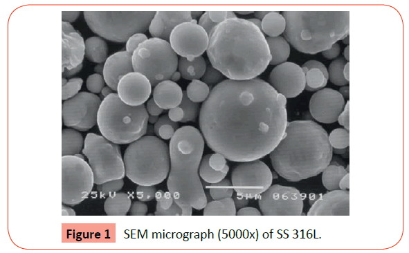
The SS 316L powder has a density of 7961 kg/m3 and having a particle size distribution of d10 = 2.99 μm, d50 = 7.68 μm and d90 = 12.63 μm (bimodal distribution). The Figure 1 shows the water atomized powder, mostly spherical that means a shape factor close to 1.
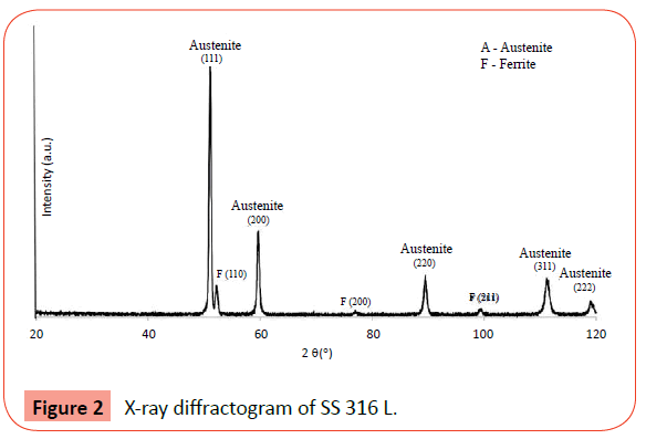
The XRD analysis (Cobalt radiation with λ = 0.1789 nm) shows that the SS 316L is mainly constituted by austenite phase (Figure 2).
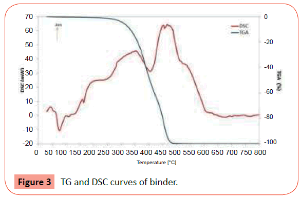
The binder is composed of polyolefin waxes, with a density of 970 kg/m3. The thermal analysis occurred under argon atmosphere, from room temperature to 800°C at a heating rate of 10°C/min. The Figure 3 shows that loss of weight (TGA curve) begins at 200°C and finishes with a total removal of binder at 475°C. On the other hand, the DSC curve shows some initial peaks that correspond to melting and evaporating of some components of the binder, while others peaks correspond to their degradation, manifested by weight loss. The range between 350°C and 450°C is an endothermic peak that requires special attention in the debinding step, because there is a significant loss weight, about 40%.
Feedstock preparation
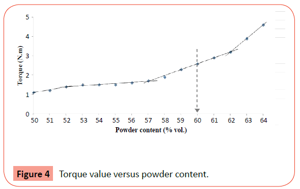
Based on binder thermal analysis, the temperature selected for optimization of the mixture was 180°C (30 rpm), with a torque value increasing with the powder additions. Four distinct regimes of shear stress variation with the powders content, corresponding to 50-52, 52-57, 57-62 and 62-64 volume contents are detected (Figure 4). During first and second regimes, the torque value increases slightly with the powder content. Then, in the two last regimes, this increasing was more significantly. The best powder: binder ratio for producing the feedstock was 60:40 (% vol.) because have high solids content and the torque value (i.e., relative density) seems appropriate for injection molding step.
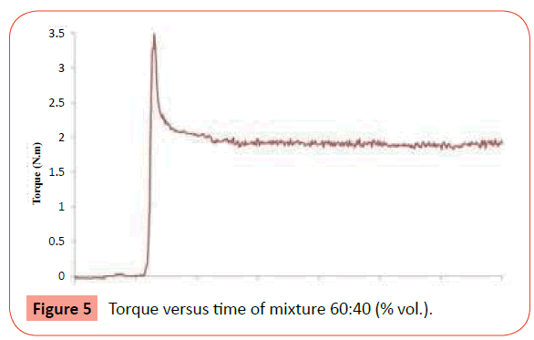
After optimization, the mixtures were produced during 30 minutes until the torque value achieved the stability (homogeneity) and the torque of the mixture 60:40% in volume was approximately 2 N.m (Figure 5).
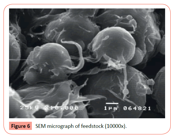
The Figure 6 shows the feedstock, where it is possible to highlight that the powders are homogeneously surrounded by the binder.
Micro-cavity surfaces (mold)
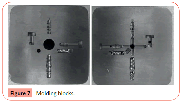
The μmold incorporates five parts that belong to a dental implant, as a single piece; to a dental implant as an assembly of three parts; and to an implant designed solely for the purpose of torque strength testing (Figure 7).
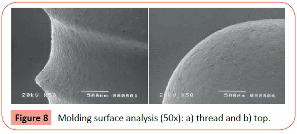
The molding surfaces were evaluated by SEM. Figure 8 shows some of the threads with a good definition and the top of the surface cavity of implant respectively.
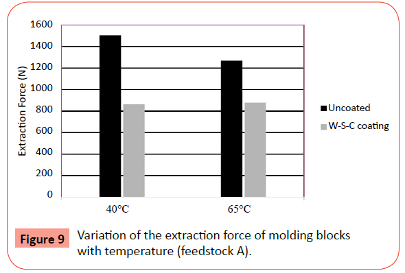
Figure 9 shows a graphic that clearly reflects the indicating the influence of coating W-S-C on the extraction force at molding temperatures of 40°C and 65°C.
The application of this coating on molding blocks allow a reduction of about 50% of the extraction forces applied to remove the mold parts.
Injection molding
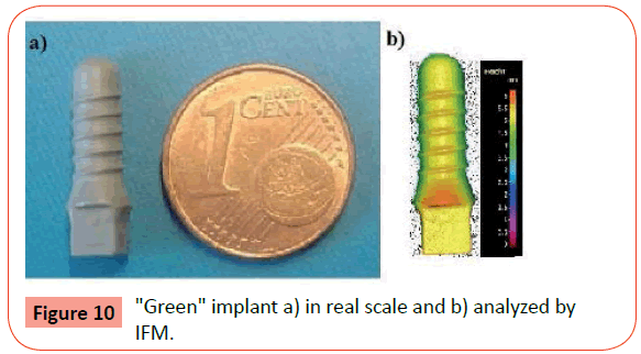
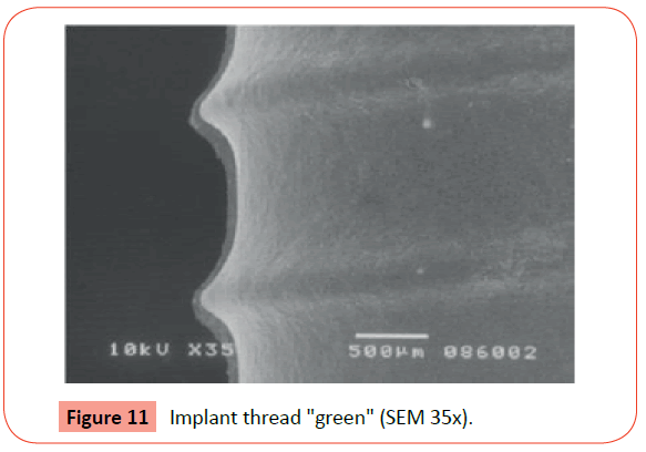
The injection parameters selected to produce the "green" samples were a mold temperature of 60°C, an injection temperature of 150°C and an injection pressure of 10 MPa. The (Figure 10 a) shows the green dental implant in real scale and the surface quality was evaluated using IFM (Figure 10 b). In (Figure 11) shows also the surface quality of the implant thread of the green by SEM.
Thermal cycles
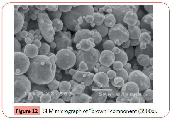
The debinding cycle occurred up to maximum temperature of 700°C, the heating rate of 1°C/min and under controlled atmosphere of Ar + H2. The SEM micrograph of "brown" (injected part after debinding) after debinding (Figure 12).
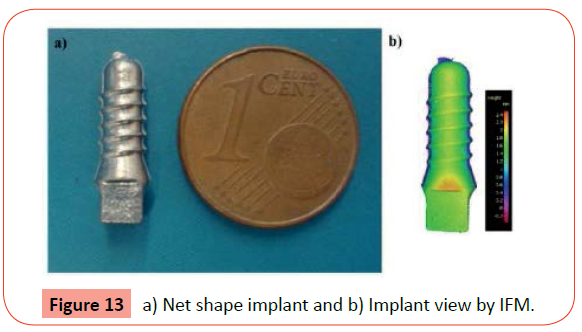
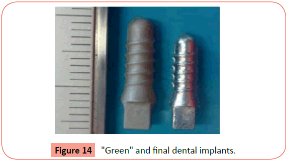
The sintering cycle was performed under the Ar + H2 atmosphere used in the debinding, where the heating rate was 10°C/min, up to maximum of 1250°C followed a holding time of 60 minutes.After sintering, the common aspect of the implant is shown in (Figure 13 a) and the morphology details by IFM in (Figure 13 b). During debinding and sintering steps, the dental implants suffered shrinkage of 13% up to 14% (Figure 14). It is also noteworthy, that the surface quality of the final dental implants had a bright aspect, similar to a polishing surface.
Osseointegrator thin film
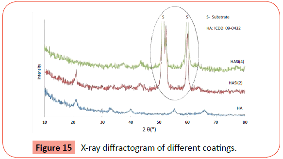
Once mechanically suitable to be implanted in bone, dental implants must present a surface with osseointegration features. Therefore the dental implants were coated with three types of thin films, with or without silicon additions (HA, HASi (2) and HASi (4)). The X-ray diffractograms (Figure 15) revealed some diffraction planes that could be identified as HA, according to ICDD card 09- 0432. This characterization highlight the nanocrystalline structure of the monolithic HA thin film and highlights the amorphization of the thin film of HA with the introduction of Si.
Tests in vitro of several HA modified by Si has a better osseointegration [12].
Evaluation mechanical strength during implantation
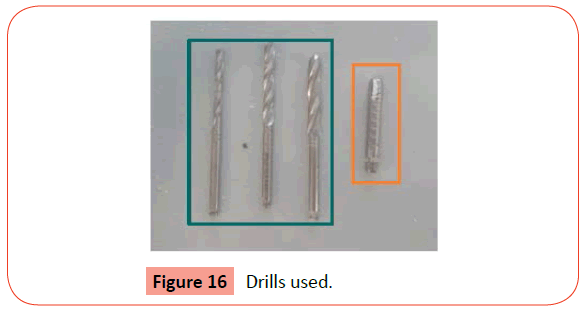
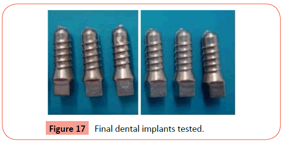
In order to guarantee the good performance during the implantation of the SS 316L coated implant an insertion torque test was carried out. This was performed by an implantologist that used drills of different diameters (2.2; 2.8 and 3.5 mm) sequentially, with rotation speed of 850 rpm to prepare the implant bed (Figure 16). In order to create a spiral to introduce the implant, it was used another drill with 4.1 mm diameter (similar to diameter of dental implant) and a speed of 30 rpm (Figure 16). Figure 17 shows the final dental implants tested.
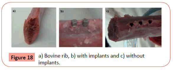
A bovine rib was selected for this test due to its cortical and spongy regions, to be similar to a human mandible bone - equivalent to bone type 2 (Figure 18 a). The sintered dental implant was introduced in rib with speed of 30 rpm and the maximum torque was less than 0.27 N.m (Figure 18 b). After removal the implants from the rib, they were physically unchanged, which means that the material adequately supported the insertion forces and for that may be acceptable for this application (Figure 18 c). The test showed that dental implants produced from SS 316L powders by MIM is mechanically suitable for this application.
A new way to producing great series dental implants that means faster and cheaper than the conventional manufacturing processes is demonstrated.
Conclusion
The MIM is suitable to produce dental implants. The molding blocks coated with dichalcogenides sulphides thin films decrease friction between injected feedstock and mol surface and consequently is needed low forces during the mold extraction, which will increase the lifetime of the molding. Moreover, the coating provides better wear strength essential to maintain micro-cavities and/or micro-details with a constant geometry. The surface of sintered dental implant has a bright aspect and a good workmanship which means that processing conditions were correctly selected. However, an implant in SS 316L has not a good osseointegration, to overcome this problem; the presence of a coating that must promote this mechanism is a good option. Thin films of hydroxyapatite doped with silicon improve the bioactivity. The 316L austenitic stainless steel and the process selected are appropriate for dental implants and this was demonstrated by torque strength test. In conclusion, a new strategy is opened up for manufacturing the least expensive dental implants, called "implants for crisis".
Acknowledgement
The research is integrated in the project BePIM through the program QREN, FEDER (COMPETE), BePIM 2, Tooling Surface. FCT for the SFRH / BD / 86216 / 2012 gr ant.
Article: Leser HG, Gross V, Scheibenbogen C, Heinish A, Salm R, Lausen M, et al. Elevation of serum interleukin-6 concentration precedes acute-phase response and reflects severity in acute pancreatitis. Gastroenterology 1991; 101:782-5. [PMID: 91317425].
References
- Combining the best that PIM has to offer to put the bite on a new approach (2006) MetalPowder Report. November, pp. 22-27.
- Haack J, Imgrund P, Hein S, Friederici V, Salk N (2010) The processing ofbiomaterials for implant applications by powder injection moulding. Powder InjectionMoulding International 4:49-52.
- Meng J, Loh NH, Fu G, Tor SB, Tay BY (2010) Replication and characterizationof 316L stainless steel micro mixer by micro powder injection molding. Journal of Alloysand Compounds 496:293-299.
- Heaney DF (2012) Handbook of metal injection molding s:l.
- Barreiros FM, Vieira MT, Castanho JM (2009) Fine tuning injection feedstockby nano coating SS powder. Metal Powder Report 64:18-21.
- Giboz J, Copponnex T, Mele P (2007) Microinjection molding of thermoplasticpolymers: a review. Journal of Micromechanics and Microengineering 17: R96-R109.
- Selada A, Manaia A, Vieira MT, Pouzada AS (2011) Effect of LBM and large-areaEBM finishing on micro-injection moulding surfaces. Int. J. Advanced ManufacturingTechnology 52:171-182.
- Pouzada AS, Ferreira EC, Pontes AJ (2006) Friction properties of mouldingthermoplastics. Polymer Testing 25:1017-1023.
- Polcar T, Evaristo M,Cavaleiro A(2009) Comparative study of the tribologicalbehavior of self-lubricating W-S-C and Mo-Se-C sputtered coatings266:388.
- Polcar T, Cavaleiro A(2011) Self-adaptive low friction coatings based on transitionmetal dichalcogenides. Thin Solid Films 519: 4037–4044.
- Ribeiro AR, Piedade AP, Ribeiro CC, Viera MT, Barbosa MA (2007)Characterization of hydroxyapatite sputtered films doped with titanium. Key EngineeringMaterials 330-332:649-652.
- Fernandes PC, Fernandes MH, Piedade AP (2014)MG63 osteoblastic cells andsilicon doped HA thin films. Acta Materialia.
Open Access Journals
- Aquaculture & Veterinary Science
- Chemistry & Chemical Sciences
- Clinical Sciences
- Engineering
- General Science
- Genetics & Molecular Biology
- Health Care & Nursing
- Immunology & Microbiology
- Materials Science
- Mathematics & Physics
- Medical Sciences
- Neurology & Psychiatry
- Oncology & Cancer Science
- Pharmaceutical Sciences
